Previous post have summarized “THE HACKATHON” in TouK. Today we will present one of the projects in greater detail – “Lidar/ROS.org based robot”. Our team wanted to either transport sandwiches or monitor WiFi quality in the office. Not deciding on the final goal we immediately saw that mobile robot platform will be needed in both cases.
Analysis
Some of our coworkers own Xiaomi vacuum cleaners. Such robot can be managed from mobile app which displays accurate map of your premises and allows to select areas that need cleaning. Xiaomi robot looked promising but two problems arose. First, the price is significant. Second, the communication protocol is not open. There are libraries on GitHub which try to reverse engineer the details but quick analysis has shown that we may end up stuck on some irritating problem and fail to realise our goals.
Closer examination of Xiaomi robot has revealed the core piece that allows it to automatically navigate around the house. It is LIDAR – laser distance measurement device. Another brand of Roomba vacuum cleaners relies on camera-like sensor instead. As computer vision seemed more difficult to approach we have decided on using LIDAR to build two-dimensional map of robot’s surroundings and navigate around the office.
Hardware
LIDAR technology is not as cheap as simple ultrasonic distance sensors but we have found two promising solutions on the market: YDLIDAR and RPLIDAR. Both brands are lines of different products with increasing capabilities and prices but the basic ones were within our budget. Quick comparison has shown that parameters of respective lowest-end models are similiar so we decided to order YDLIDAR because it was the quickest to ship from Amazon to Poland.
One thing to note is that core LIDAR component can be acquired for even lower price but such device will have fixed line of sight. Our chosen model, just like the one built into Xiaomi, has full 360 degree rotating head. It makes 5 to 10 rotations per second scanning 5 thousand points in that time. The output data stream contains angle and distance for each measured point.
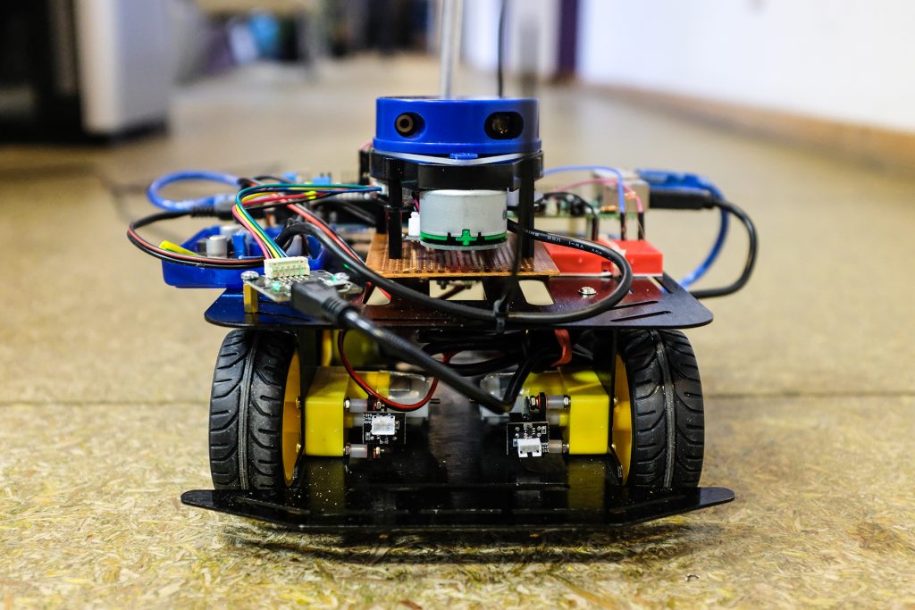
For our robot we needed a mobile base. Common choice is base with two motorized wheels plus one or two support wheels that freely rotate in all directions giving minimal friction. We discarded that option because such simple bases for amateur constructions have weak motors and we had quite a load to put on top. Professional bases with two powerful motors are expensive. In the end we bought four-wheeled base with independent low-grade DC motors driving each wheel. The wheels are not steerable – turning is done like in a tank. Our kit was also equipped with two motor encoders – devices that measure how many times wheel has rotated – we will try to use that knowledge later.
According to the manufacturer’s data our base can bear 800 grams of load. We have put there:
- Raspberry Pi 3 B+, the most powerful model available
- Arduino Uno
- 4-channel motor shield for Arduino
- YDLIDAR
- LiPo battery pack
- DC voltage regulators
We have decided that our robot should be fully autonomous so all the data processing will happen on-board using Raspberry Pi. It was connected via USB with Arduino which was used to control motors using standard Arduino-compatible controller. We knew that RPi has GPIO pins that can be used to control peripherals like Arduino would but we wanted to separate the concerns and use all the power of RPi for other responsibilities.
Software
We have assembled a mobile base with YDLIDAR mounted on top but YDLIDAR itself cannot build a complete map of our office and navigate around it. We needed algorithms that could interpret incoming data stream of distance measurements and convert it into usable map. We have found the ROS.org project. It is called Robot Operating System but instead of being full OS it is Linux-based framework – collection of tools and algorithms that makes programing robots easier. As hackathon was designed to deliver working products each team was given time to prepare before the main event. We have spent that time on learning ROS and gathering main components for our robot.
ROS is capable of handling LIDAR data, building a map and performing navigation of robot. If some feature is not available in ROS it can be added by coding of a “node” – separate program that communicates with another nodes using “topics” – ordered streams of events. Fortunately, all parts of our use case were already available as standard ROS nodes, topics and event types. YDLIDAR’s manufacturer provided custom ROS-compatible node which handles low-level interaction with device. There is also an Arduino relay library that makes it possible to write Arduino code that directly subscribes and publishes events to ROS topics.
Having written less than 100 lines of ROS nodes’ launch configuration in XML and less that 100 lines of Arduino code, we were able to remote control our robot and see the map on screen. We have used separate notebook which handled joystick controller and displayed a map. The notebook was configured as ROS slave connected over WiFi to ROS master running on RPi. Below we show how simple it was to setup USB joystick controller:
<launch>
  <node pkg="joy"
        type="joy_node"
        name="ross_joy"
        respawn="true" >

    <param name="autorepeat_rate" value="10" />
  </node>

  <node pkg="teleop_twist_joy"
        type="teleop_node"
        name="ross_teleop"
        respawn="true" >

    <param name="scale_linear" value="0.3" />
    <param name="scale_angular" value="0.3" />
  </node>
</launch>
Unexpected problems and spontaneous solutions
During the hackathon days we have experienced some difficulties. As we were not able to test full robot assembly before the main event, some problems have surfaced very late in the process and dirty solutions must have been quickly hacked.
First problem: power source. During initial tests we used 24V DC power source connected to wall power. It had to be calibrated because internal protection cut off the power when current drawn by motors become too high. We also had 12V LiPo battery for final tests and show. Different input voltages were converted by on-board step-down regulators. One has provided 5V needed by RPi, Arduino and YDLIDAR. Second regulator fed 10V to the motors. During the tests it appeared that YDLIDAR cannot be powered from RPi’s USB port because its voltage was not stable enough. In the end we have connected YDLIDAR power input directly to 5V output from appropriate regulator.
Second problem: jerky movement. We thought (because ROS wiki suggested so) that it would be a good design to include PID controller driving the wheels. It is an algorithm that tries to maintain one value (in our case: measured actual speed of wheels) by varying another value that directly influences the first (in our case: power applied to motors). After some tests we have disabled PID controller because it requires fine tuning to behave correctly. As our rotational wheel encoders report only 10 ticks per revolution, the PID was confused by such low measurement resolution and tried to vary motor power too sharply rendering smooth movement impossible. We believe it can be tuned properly but during the hackathon we have setup joystick to directly control motors’ power, and not robot’s target speed, making human operator responsible for adjustments.
Third problem: faulty encoders. Our will to have wheel encoders originated not from possibility to enable PID controller, but from opportunity to increase mapping precision. Knowing how much robot has moved can help to better correlate data from multiple laser scans, producing more accurate map. Unfortunately, one of encoders appeared to work incorrectly, reporting too few ticks per revolution. Not having much time to investigate that we decided to disconnect encoders completely.
Making maps
At the beginning of second day we have already known main limitations of hardware and software and decided that we will use those parts that work predictably. We confirmed that PID controller was not neccessary for our purposes and mapping can be done using laser data only. We decided to enable simplest mapping algorith in ROS – a method called Hector SLAM. We could start first tests.
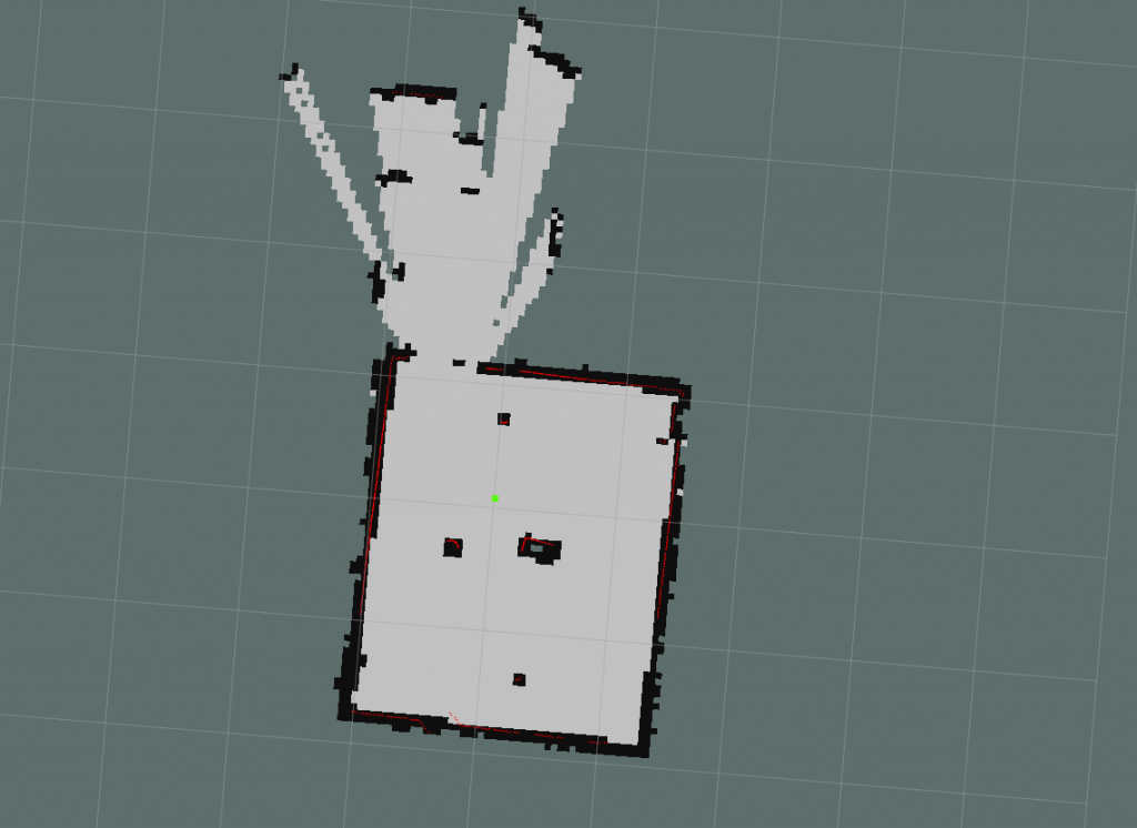
At first we mapped small room with two desks in it and a glass door. We have put additional objects in the middle to see how their presence would be handled. Everything worked smoothly using default parameters of Hector method. We also confirmed that it is easy to overlay map with additional data coming from sensors – in our case it was simple photoresistor measuring light intensity in the room.
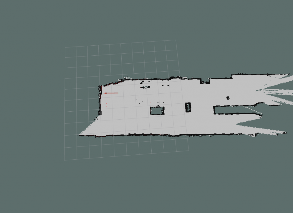
Then we moved onto mapping bigger area – the hall between rooms. There is additional wall dividing it in the middle and a pillar. We added few other objects. During the tests robot was wired to the power source. We tested how to move our bodies around so to not interfere with the measurements. It appeared that after mapping initial fragment it is safe to walk around and Hector algorithm will ignore moving objects. Only after staying for too long in the same place our legs started to be included as part of the map.
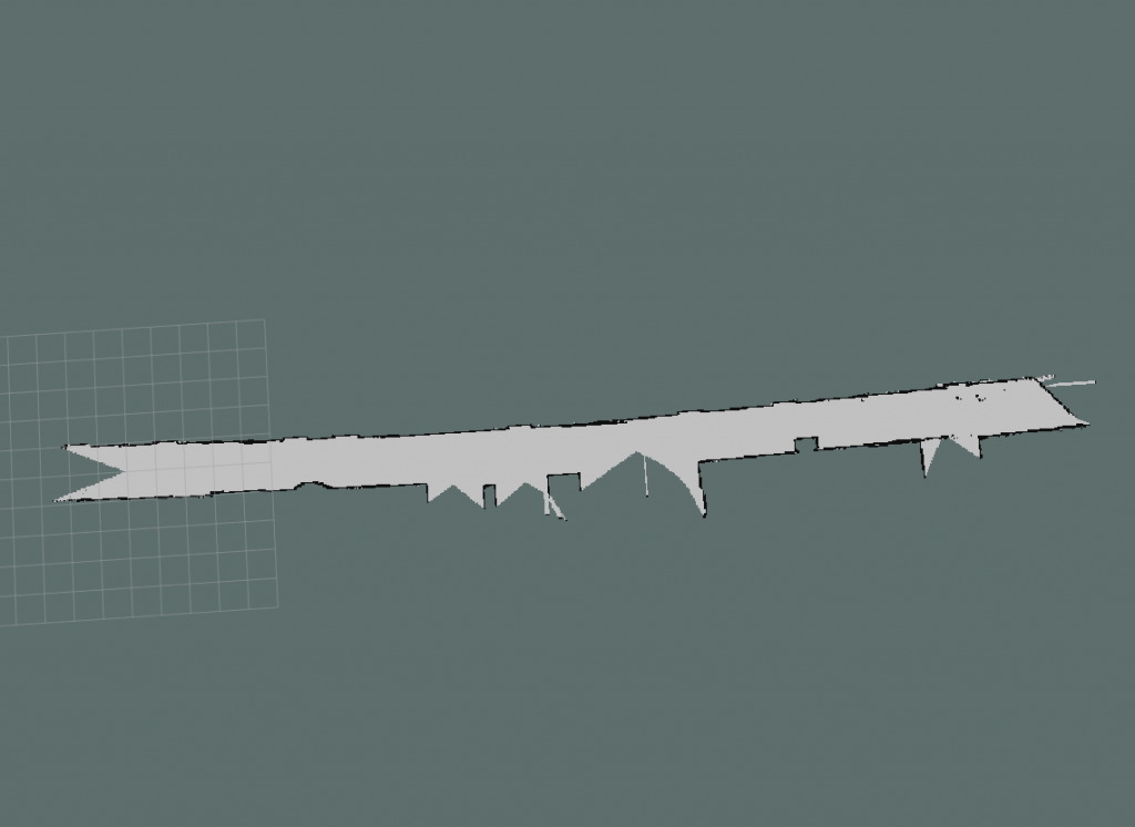
Final test shows straight corridor. Its map is bended and we are not sure of the cause. It may be related to slow scan rate of YDLIDAR which accumulates error during robot’s movement.
Future work
Having learnt ROS before the hackathon and solved mostly hardware-related problems during the event, we have shown that map building is possible even with simple setup. We would like to expand the algorithmic part of the solution, enabling our robot to autonomously move in the office environment. Proper navigation components are already available in ROS.
Conclusions
ROS is a powerful tool that can be used both by amateurs and proffesionals. Its sophisticated architecture allows for complex definitions and management of industrial-grade robots, but can also fit in quick and dirty home projects. For us the biggest challenges lied in the hardware layer, but having electronic engineer on the team helped to connect all the parts together. All Ross team members are happy with results and wish to continue the project.